About Theory
Thanks to the improvements of electron microscopes by aberration correction, it is now possible to investigate materials at the scale of individual atoms even at low acceleration voltages.
For quantitative analysis, a detailed understanding of the imaging process is mandatory, which includes the properties of electron source, the interaction of the electron beam with the sample, the transfer properties of the image forming system including the influence of lens aberrations, and the response properties of the detector system.
Consequently, image calculations have become an inevitable tool for the analysis of HR-TEM images, the optimization of imaging conditions, and the refinement of theoretical models for the sample under investigation. For low-voltage HR-TEM, numerical image calculation is particularly important, because the relation between object structure and image intensity is non-linear even for extremely thin samples [1] and dynamical (plural) electron scattering of the incident electrons within the atomic potential of the object needs to be considered. In addition, inelastic scattered electrons (e.g. by plasmons) are non-negligible at low voltages. Accordingly, these scattering processes must be included in the calculation to obtain reliable results.
Furthermore, for beam-sensitive materials, the resolution limit becomes dose dependent due to the low S/N-ratio. [2] If samples are observed using low dose, the resolution and visibility of particular structural features is strongly depending on the dose imposed to the sample, which must thus be a parameter of image simulation.
SALVE research in theory has contributions to the Work Packages "HRTEM", "Spectroscopy", "Software development and data evaluation", and "outreach". In Work Package "HRTEM" of SALVE I-II some of the most important research fields have been advanced further:
- The TEM image of graphene has been calculated as a function of energy spread of the imaging electrons and chromatic aberration coefficient using density functional theory. [1]
- It has been demonstrated that the weak-phase-object approximation cannot be used for the imaging of graphene with slow electrons (20 kV).
- We have implemented a simple model to treat incoherent image formation by inelastically scattered electrons in standard multislice calculations. [3]
- We have studied the influence of dose and sampling rate on the final contrast, S/N-ratio, and resolution in the image [4].
Following our calculations, the contrast obtained by CC/CS correction (taking into account the limitation due to the unavoidable Johnson noise [5] is higher than what can be obtained by CS correction and monochromatization (see Fig. 1 for comparison).
Figure 1: Calculated graphene contrast obtained at 20 kV in the image of a CC/CS-corrected microscope (1st row) and in a microscope equipped with a monochromator and a CS-corrector (2nd row), a) experimental zero-loss spectrum obtained in a Cc-corrected microscope, b) optimum bright-atom contrast and c) optimum dark-atom contrast obtained in the CC/CS-corrected microscope, d) zero-loss spectrum with a FWHM of 0.1 eV produced by the monochromator, e) and f) optimum bright-atom contrast and dark-atom contrast obtained in the monochromated microscope with CC = 1.5 mm, g) line profiles taken in b) and e), h) line profiles taken in c) and f). Optimum contrast values (%) for bright-atom and dark-atom imaging are given in the lower right corner of each image. The calculations for CC/CS - corrected and monochromated imaging are performed by assuming an image spread with std. deviation σε = 47 pm. During SALVE I-II we have worked on THEORY in Work Package B: "Spectroscopy", we were dealing with measuring of aberrations and numerical post-processing method for removing the effect of anti-symmetric residual aberrations in high-resolution transmission electron microscopy images of weak scattering objects. [6, 7]" Theory in Work Packages C: "Software development and data evaluation" and E: "Outreach" will be new topics in SALVE III. Theoretical research in SALVE III has topics in Work Package (A), (B), (C) and (E), which will be described here in detail. In the topics of Work Package (A) the simulation developed in SALVE I-II will be validated against experimental data and the simulation of the effect of aberrations on the image of scattering objects will be improved.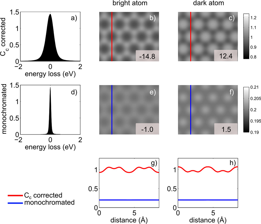
Topics in Theory (SALVE III)
Work Package (A: HRTEM) - Validation and improvement of image simulation
Topic A1 - Comparison of image calculation and experiments
In order to test and validate the results of the image calculation developed in SALVE I-II, experiments will be carried out at different instruments using standard samples such as graphene and crystalline Si. The performance of CC/CS corrected instruments at low voltages will be evaluated using the microscope PICO at Ernst-Ruska-Center Julich, Germany operated at 50 and 80 kV. The contrast enhancements due to CC corrections compared to instruments using monochromators and conventional CS correction will be evaluated using the FEI Titan at Ulm operated at 80 kV. Starting from 2016 the performance of the dedicated SALVE corrector implemented into the Titan SALVE III TEM will be investigated especially in the low voltage regime of 20 to 40 kV. Energy-filtered experiments of thicker samples such as crystalline Si will be carried out using also Plasmon imaging (with and without CC) to validate our results of inelastic image calculations by comparison with benchmark experiments. One practical task in this Work Package will be to accompany the acceptance test of the SALVE III microscope scheduled for March 2016 at CEOS.
Topic A5 - Improved HR-TEM image evaluation
In order to be able to determine the structure if the amorphous state and of defined defects and their dynamics, an image processing software will be developed which allows the determination of ring statistics and nearest neighbor analysis in an automated way.
Work Package (B: Spectroscopy) - Simulation of the spectroscopic signal in low-voltage TEM
The aim in Work Package (B) of SALVE III theory is the optimization and application of electron energy-loss spectroscopy (EELS) at low acceleration voltages on the basis of theoretical calculations for low-dose measurements. In particular, the spectroscopic signal from sandwich structures will be simulated. A layered electron-gas model is developed using dielectric theory. Ab-initio calculations in the framework of density-functional theory are used for quantitative, parameter-free predictions of the dielectric response.
Work Package (C: Software development and data evaluation) - Development of automatic image evaluation for the determination of aberrations
In Work Package (C) the automatic analysis of images of amorphous samples will be developed. Beside the accurate determination of aberrations. In SALVE III, we intend to further evaluate this method to measure accurately residual anti-symmetric aberrations and perform systematic studies to determine the long-time stability of the correction status in HRTEM images.
Work Package (E: Outreach) - Improvement of quantitative TEM image simulation: Making SALVE I-II image calculation available to the community
In Work Package (E) the image calculation developed in SALVE I-II will be incorporated in standard simulation tools to make it available for every-day use in the community by incorporating them in commonly used simulation programs. Several programs have been developed for TEM, e.g. JEMS [8], TEMSIM [9], STEMSIM [10], QSTEM [11], or MUSLI [12]. These programs consider elastic and quasi-elastic (phonon-excitation) scattering of the electron beam. To make our results available and reusable, the new techniques will be implemented in the image-calculation software QSTEM [11], working in collaboration with the Ch. Koch (HU Berlin). The enhanced program will have features such an easy import of the MTF of detector and EEL spectra to include realistic dampening envelopes caused by the camera and inelastic scattering within the samples. By implementation of the methods in a widely-known image calculation program, we expect a spreading of those techniques within the TEM community, interested in low-voltage HRTEM to have more quantitative image calculations not only for elastic images but also for inelastic (energy-filtered) images.
References
- Lee, Z., Meyer, J. C., Rose, H., & Kaiser, U. (2012). Optimum HRTEM image contrast at 20kV and 80kV—Exemplified by graphene. Ultramicroscopy, 112: 39-46, doi: 10.1016/j.ultramic.2011.10.009
- Rose, H. H. (2009). Future trends in aberration-corrected electron microscopy. Philosophical Transactions of the Royal Society of London A, 367: 3809-3823, doi: 10.1098/rsta.2009.0062
- Lee, Z., Rose, H., Hambach, R., Wachsmuth, P., & Kaiser, U. (2013). The influence of inelastic scattering on EFTEM images—exemplified at 20kV for graphene and silicon. Ultramicroscopy, 134:102-112, doi: 10.1016/j.ultramic.2013.05.020
- Lee, Z., Meyer, J. C., Rose, H., & Kaiser, U. (2012). Optimum HRTEM image contrast at 20kV and 80kV—Exemplified by graphene. Ultramicroscopy, 112: 39-46, doi: 10.1016/j.ultramic.2011.10.009
- Uhlemann, S., Müller, H., Hartel, P., Zach, J., & Haider, M. (2013). Thermal magnetic field noise limits resolution in transmission electron microscopy. Physical review letters, 111: 046101, doi: 10.1103/PhysRevLett.111.046101
- Biskupek, J., Hartel, P., Haider, M., & Kaiser, U. (2012). Effects of residual aberrations explored on single-walled carbon nanotubes. Ultramicroscopy, 116: 1-7, doi: 10.1016/j.ultramic.2012.03.008
- Lehtinen, O., Geiger, D., Lee, Z., Whitwick, M. B., Chen, M. W., Kis, A., & Kaiser, U. (2015). Numerical correction of anti-symmetric aberrations in single HRTEM images of weakly scattering 2D-objects. Ultramicroscopy, 151: 130-135, doi: 10.1016/j.ultramic.2014.09.010
- Stadelmann, P. A. (1987). EMS-a software package for electron diffraction analysis and HREM image simulation in materials science. Ultramicroscopy, 21: 131-145, doi: 10.1016/0304-3991(87)90080-5
- Kirkland, E. J. (1998) Advanced Computing in Electron Microscopy. NY: Plenum.
- Rosenauer, A., & Schowalter, M. (2008). STEMSIM—a new software tool for simulation of STEM HAADF Z-contrast imaging. In Microscopy of Semiconducting Materials, 2007: 170-172. Springer Netherlands, doi: 10.1007/978-1-4020-8615-1_36
- Koch, C. T. (2002). Determination of core structure periodicity and point defect density along dislocations. PhD dissertation, Arizona state university
- Chuvilin, A., & Kaiser, U. (2005). On the peculiarities of CBED pattern formation revealed by multislice simulation. Ultramicroscopy, 104: 73-82, doi: 10.1016/j.ultramic.2005.03.003