About Instrument Development
Research and developments on the increase and optimization of resolution and contrast by means of novel correctors as well as the improvement of environmental conditions to realize the instrumental resolution is a main topic in SALVE. In SALVE III, the CC/CS corrector optimized for the low voltage range 20 - 80 kV during SALVE II will be advanced further. During SALVE II, SALVE partner CEOS company Heidelberg has identified the source of a previously inexplicable noise, which produces additional image spread [1].
Image spread in the electron microscope is now well understood
This discovery explained why previously built CC/CS-corrector didn't meet the expectations. Because the problems is now well-understood, this noise could be reduced by appropriately designing the related parts of the corrector. The reduction of image spread cause by Johnson-Nyquist-noise, which is part of Work Package A: "HRTEM" could be successfully accomplished in the SALVE II project.
Reduction of Johnson-Nyquist-noise in SALVE II
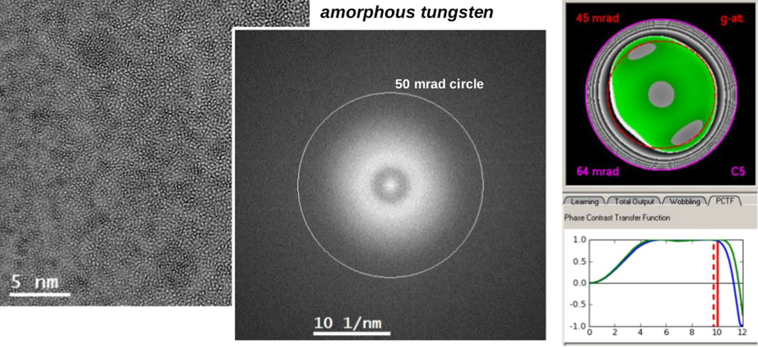
The direct comparison of CC/CS-corrected images before and after the redesign in Fig. 1 exemplifies the resolution improvement which was achieved by making the beam path less sensitive to the Johnson-Nyquist-noise. The Young Fringes resolution shows information transfer to almost 50 mrad objective aperture: The electron optical design enables phase contrast imaging with a hitherto not-existing quality.
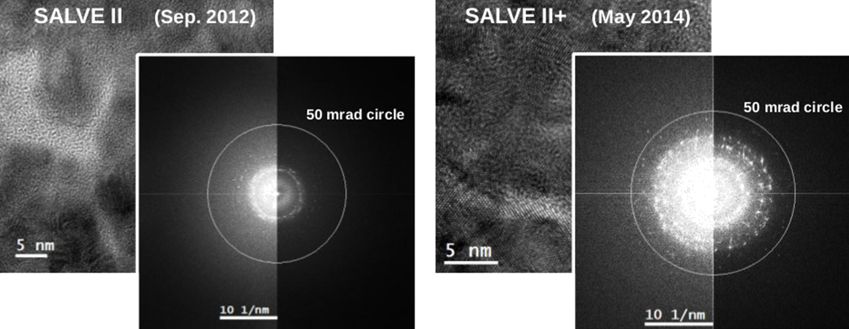
The performance of the SALVE II CC/CS corrector
In addition to short-term stability another topic in Work Package A: "HRTEM" was the improvement of the long-term stability of power supplies, which is essential to avoid drift of aberrations and thus to avoid the necessity to retune the corrector during time consuming experiments (e.g. focus series, time series, etc.). In SALVE II the electronic supplies have been changed and improved. These measures have significantly enlarged the duration of the stability of the corrected state.
Work Package A: "HRTEM" of SALVE I-II also comprised the investigation of the environmental conditions that are necessary for the operation of a low-voltage TEM. Beside highly stable power supplies, the microscope requires also sufficient suppression and/or shielding of parasitic mechanical, acoustic and electromagnetic vibrations for the stability of the electron optics. Parameters for a vibration-isolated room with automated control of room and microscope parameters, which will be established in the frame of SALVE III, have been determined in SALVE I-II.
In Work Package B: "Spectroscopy", the SALVE team at Ulm University has gained extensive experience using the ω-q mode with an in-column energy filter during SALVE I-II, which is required for the implementation and optimization of parallel EELS recording using the Titan SALVE III microscope.
The advantages of the ω-q mode
We have developed a set of calibration procedures for the in-column filter in the SALVE-I microscope (Libra based platform) and obtained reproducible results for the momentum-dependent energy-loss function of graphene with a momentum resolution of less than 0.1 Å-1 and an energy resolution of 0.2 eV [3].
In Work Package C: "Software development and data evaluation", a user-friendly graphical user interface has been programmed by CEOS company, in which the required tools for the alignment of the CC/CS corrector have been included so that the parameters can be controlled appropriately.
As Work Package D: Development of in-situ TEM, in-situ microscopy at low voltages has been an active field of research in SALVE I-II and worldwide in the last years [e.g. 4 - 10]. At high temperatures of 2000 K and more [6, 10], the crystallisation of amorphous adsorbates and the annealing and fusing of cracks in graphene were observed in-situ. Furthermore, samples like graphene could be cut, drilled and sculptured by the electron beam [5, 8] or the growth of graphene [7] and the oxidation processes caused by noble metal catalysts [11] or dehydrogenation of Pd [12] were imaged at close to atomic resolution.
Topics in Instrument Development (SALVE III)
Instrument development in SALVE III has topics in all Work Packages, which will be described here in detail. For specifications of the SALVE III microscope click here.
Topics in Work Package (A: HRTEM) - Advances in environment, TEM column and aberration correction
Topic A1 - Optimized electron optics
The existing corrector in its present form has been modified to fit into the TEM column of the new FEI-SALVE platform. The basic electron optics of the corrector remains unchanged, while the mechanical components are adapted to the new base instrument.
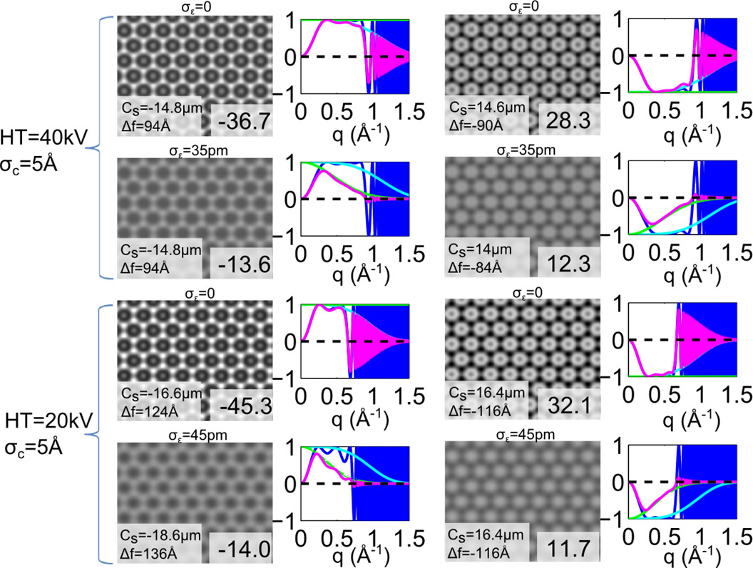
To demonstrate the resolution expectation, we compare in Fig. 3 calculated phase-contrast images for the existing residual focus spread dampening without image spread (ideal case of CC correction) with images that are additionally limited by the currently unavoidable dampening by the image spread σε. Experimental images match with our calculated images using the given focus spread and image spread for the envelope function [13, 14]. The theoretical images with image spread σε = 35 pm at 40 kV, and σε = 45 pm at 20 kV show that about 14% contrast can be reached for positive C5 giving white atom contrast and 12% giving dark atom contrast, as for the predecessor corrector of SALVE II+, the CEOS achroplanatic corrector CCOR+. For all voltages the SALVE II+ corrector demonstrates its advantage over the CCOR+. A system with negative C5 must use a positive C3 for compensation and has, therefore, to use underfocus conditions (dark-atom contrast) for achieving optimum transfer of the spatial frequencies. The SALVE II+ corrector has a positive C5 and achieves an optimum frequency transfer with negative C3 and overfocus conditions (bright-atom contrast). Finally, the SALVE II+ design is superior to that of the CCOR+ with respect to correcting off-axial aberration at very low voltages between 20 and 40 kV. In that range the SALVE II+ corrector can correct off-axial aberrations for a wider field of view.
Topic A2 - Power supplies and environment
After the investigation of the environmental conditions that are necessary for the operation of a low-voltage TEM including the Instrument Development on the power supplies during SALVE I-II, a vibration-isolated room with electrical shielding as well as automated control of room and microscope parameters will be developed and built at the University of Ulm during SALVE III.
Topics in Work Package (B: Spectroscopy) - New spectroscopy methods
In SALVE III, the aim of this Work Package is the implementation and optimization of parallel EELS recording for the Titan SALVE III microscope equipped with a post-column energy filter. First experiments will be carried out at the standard Titan at Ulm University.
Topic B1 - Calibration and evaluation
- adopt our existing calibration procedures for the Gatan post-column energy filter
- assess and minimize the image distortions of the energy filter in ω-q and ω-x mode
- evaluate the stability of the filter and the reproducibility of the calibration
- compare the performance of post-column and in-column energy filters (in cooperation with SALVE associated member R. Schröder from the University Heidelberg, Germany)
Topic B2 - Line illumination for space-dispersive EELS
To minimize the electron dose, apertures behind the sample should be avoided. For space-dispersive EELS this can be achieved using an illumination in form of a thin line. We will implement and compare several methods to produce a shaped electron beam using
- a slit aperture in the condensor system (cooperation with R. Schröder, University Heidelberg)
- an elliptic (stigmatic) illumination similar as for holography
- a focused electron beam moving rapidly along a line as used for adjustments of the STEM detector settings (brightness and contrast). This combines the high-spatial resolution of STEM with the fast acquisition in ω-x mode.
Topic B3 - Optimized apertures for angular-dispersive EELS
Parallel recording becomes even more powerful if the aperture geometry can be freely designed. We evaluate and test new geometries, optimized for
- an increased signal at large scattering angles (wedge shaped)
- a fast momentum calibration in ω-q mode (line of small, round apertures)
- a simultaneous measurement of different crystallographic directions (V-shaped, for EMCD).
Topics in Work Package (C: Software development and data evaluation) - Corrector adjustment software development
In SALVE I-II, software for the adjustment of the corrector has been developed. This activity will be continued in SALVE II in order to realize a user-friendly graphical user interface for an intuitive and simple adjustment as required for daily-basis operation.
Topics in Work Package (D: In-situ TEM and devices) - Modifying MEMS-based cartridges for in-situ heating and electrical probing
In in-situ microscopy, we are focussing on imaging structural variations under the supply of an electrical current. Care will be taken to improve the vacuum and leave holder flexibility in the microscope. More information about these modifications are available under Tools/SALVE III microscope. TEM-holders are considered to be the next bottlenecks beside the sample preparation and the microscope column. MEMS (microelectromechanical systems)-based holder allow simpler electrical contracting and much more controlled local heating without strong drift. The work during SALVE I-II is important pre-work for this topic.
A low-noise platform for in situ structural and electrical characterization in the microscope will be developed. The geometry of the cartridges for the Microelectromechanical systems (MEMS) sample holder "NanoEX I/V" produced by FEI will be modified based on the expertise gained within SALVE I-II to allow electrical probing. Using this SALVE III tool prototypes will be produced by FIB-lithography. After prototyping, the optimized MEMS cartridges will be produced using optical lithography at the Institute for Optoelectronics at Ulm University (Director: Ferdinand Scholz), who is SALVE associated member.
Topics in Work Package (E: Outreach) - Technology transfer
Technology transfer effectively morphs scientific discoveries and research tools into new understanding and further on into commercially viable products. In SALVE III we are planning to make most innovative research and technology solutions highly available to strengthen economy (technical equipment as well as calculation software).
References
- Uhlemann, S., Müller, H., Hartel, P., Zach, J., & Haider, M. (2013). Thermal magnetic field noise limits resolution in transmission electron microscopy. Physical review letters, 111: 046101, doi: 10.1103/PhysRevLett.111.046101
- Reimer, L., Fromm, I., & Rennekamp, R. (1988). Operation modes of electron spectroscopic imaging and electron energy-loss spectroscopy in a transmission electron microscope. Ultramicroscopy, 24: 339-354, doi: 10.1016/0304-3991(88)90126-X
- Wachsmuth, P., Hambach, R., Kinyanjui, M. K., Guzzo, M., Benner, G., & Kaiser, U. (2013). High-energy collective electronic excitations in free-standing single-layer graphene. Physical Review B, 88: 075433, doi: 10.1103/PhysRevB.88.075433
- Cretu, O., Botello-Mendez, A. R., Janowska, I., Pham-Huu, C., Charlier, J. C., & Banhart, F. (2013). Electrical transport measured in atomic carbon chains. Nano letters, 13: 3487-3493, doi: 10.1021/nl4018918
- Algara-Siller, G., Santana, A., Onions, R., Suyetin, M., Biskupek, J., Bichoutskaia, E., & Kaiser, U. (2013). Electron-beam engineering of single-walled carbon nanotubes from bilayer graphene. Carbon, 65: 80-86, doi: 10.1016/j.carbon.2013.07.107
- Barreiro, A., Borrnert, F., Rummeli, M. H., Buchner, B., & Vandersypen, L. M. (2012). Graphene at high bias: Cracking, layer by layer sublimation, and fusing. Nano letters, 12: 1873-1878, doi: 10.1021/nl204236u
- Peng, Z., Somodi, F., Helveg, S., Kisielowski, C., Specht, P., & Bell, A. T. (2012). High-resolution in situ and ex situ TEM studies on graphene formation and growth on Pt nanoparticles. Journal of Catalysis, 286: 22-29, doi: 10.1016/j.jcat.2011.10.008
- Robertson, A. W., Allen, C. S., Wu, Y. A., He, K., Olivier, J., Neethling, J., ... & Warner, J. H. (2012). Spatial control of defect creation in graphene at the nanoscale. Nature communications, 3: 1144, doi: 10.1038/ncomms2141
- Bi, H., Yin, K., Xie, X., Zhou, Y., Wan, N., Xu, F., ... & Ruoff, R. S. (2012). Low temperature casting of graphene with high compressive strength. Advanced Materials, 24: 5124-5129, doi: 10.1002/adma.201201519
- Westenfelder, B., Meyer, J. C., Biskupek, J., Kurasch, S., Scholz, F., Krill III, C. E., & Kaiser, U. (2011). Transformations of carbon adsorbates on graphene substrates under extreme heat. Nano letters, 11: 5123-5127, doi: 10.1021/nl203224z
- Yoshida, H., Kuwauchi, Y., Jinschek, J. R., Sun, K., Tanaka, S., Kohyama, M., ... & Takeda, S. (2012). Visualizing gas molecules interacting with supported nanoparticulate catalysts at reaction conditions. Science, 335: 317-319, doi: 10.1126/science.1213194
- Yokosawa, T., Alan, T., Pandraud, G., Dam, B., & Zandbergen, H. (2012). In-situ TEM on (de) hydrogenation of Pd at 0.5–4.5 bar hydrogen pressure and 20–400° C. Ultramicroscopy, 112: 47-52, doi: 10.1016/j.ultramic.2011.10.010
- Krivanek, O. L., Lovejoy, T. C., Dellby, N., Aoki, T., Carpenter, R. W., Rez, P., ... & Crozier, P. A. (2014). Vibrational spectroscopy in the electron microscope. Nature, 514: 209-212, doi: 10.1038/nature13870; Krivanek, O. L., Lovejoy, T. C., Aoki, T., Crozier, P. A., Rez, P., Egerton, R. F., Dellby, N. (2014). STEM of phonons and very light elements by < 20 meV resolution EELS. Abstract MMC
- Lee, Z., Rose, H., Lehtinen, O., Biskupek, J., & Kaiser, U. (2014). Electron dose dependence of signal-to-noise ratio, atom contrast and resolution in transmission electron microscope images. Ultramicroscopy, 145: 3-12, doi: 10.1016/j.ultramic.2014.01.010